
web solarStore


Outback Flexmax 80 Charge Controller
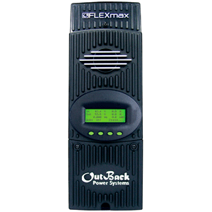
- Flexmax 80 Charge Controller
- The Outback Flexmax 80 maximum power point tracking charge controllers offers an efficient, safe, multi-stage recharging process that prolongs battery life and assures peak performance from a solar array. Each Outback Flexmax 80 charge controller allows customized battery recharging. With backlit LCD display screen with 80 characters has a memory that will hold the last 128 days of operational data. Voltage step-down capability allowing a higher PV array voltage configuration with a manual and auto-equalize cycle for the batteries. Each Outback Flexmax 80 Charge Controller also features Continuous Maximum Power Point Tracking (MPPT), which seeks out the maximum power available from a solar array and uses it to recharge the batteries. Without this feature, the solar array does not operate at the ideal operating voltage and can only recharge at the level of the battery voltage itself. Each Charge Controller continuously tracks the array’s maximum operating power.
- Only: Buy Now
- Product Details:
- Specifications:
- Videos:
- Documents:
Outback Flexmax 80 Charge Controller
| Model | Part Number | Input Current | System Voltage | Type | Shipping Weight |
| Flexmax 80 | 02002020 | 80 Amps | 12 / 24 / 48 VDC | MPPT | 15 lbs |
The FLEXmax MPPT software algorithm is both continuous and active, increasing PV array power yield up to 30% compared to non-MPPT controllers. FLEXmax charge controllers can operate at their maximum rated current in ambient temperatures as high as 104°F (40°C) and can be used with battery systems from 12 to 60 VDC with solar open-circuit voltage as high as 150 VDC. The controller’s set points are fully adjustable to allow use with virtually any battery type, chemistry, and charging profile.
FLEXmax controllers come standard with a 4-line, 80-character backlit LCD screen that displays solar system performance with a 128 day history and is also used for programming and monitoring the system’s operation. For larger systems, OutBack’s MATE series of system controllers enables monitoring of up to 8 FM controllers from up to 300 feet away. The MATE also includes an opto-isolated RS-232 port for connection to a PC or laptop for data logging and system monitoring.
Both controllers have a programmable AUX relay that can be used for control functions such as battery enclosure fans, generator starting, or load control. The AUX output is 200 mA at 12 VDC. Use it to power a separate relay with a 12 VDC coil if you need to control more amperage or to control voltages (AC or DC) other than 12 VDC.
FLEXmax charge controllers are covered by a 5-year standard warranty and are Listed to UL 1741 and C22.2 No. 107.1.

What's In The Box
- Outback, FM80-150VDC MPPT Charge Controller, 80A, 12 / 24 / 48 VDC
![]() Outback Controllers ship in 3 - 5 business days after funds clear.
Outback Controllers ship in 3 - 5 business days after funds clear.
| Maximum Solar Array |
| Battery Bank Voltage | 12 VDC | 24 VDC | 48 VDC | |
| Max. Solar Array | FM 60 | 750 Watt | 1,500 Watt | 3,000 Watt |
| FM 80 | 1,000 Watt | 2,000 Watt | 4,000 Watt |
| Optional Accessories | Part # | Price | |
| Outback Temperature Sensor |
BP9500102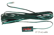 |
||
| OutBack Mate 3 Remote Control for OutBack Inverters and Charge Controllers |
BP9578732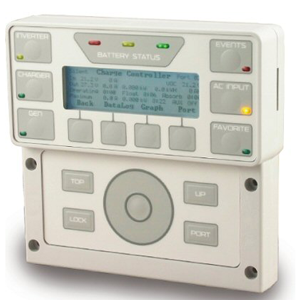 |
Outback Flexmax 80 Charge Controller Specifications |
| FLEXmax 80 Specifications | Flexmax 80 Specifications | |
|---|---|---|
| Nominal Battery Voltages | 12, 24, 36, 48, or 60 VDC (Single model - selectable via field programming at start-up) | 12, 24, 36, 48, or 60 VDC (Single model - selectable via field programming at start-up) |
| Maximum Output Current | 80 amps @ 104° F (40°C) with adjustable current limit | 60 amps @ 104° F (40°C) with adjustable current limit |
| Maximum Solar Array STC Nameplate | 12 VDC systems 1250 Watts / 24 VDC systems 2500 Watts / 48 VDC systems 5000 Watts / 60 VDC systems 6250 Watts | 12 VDC systems 900 Watts / 24 VDC systems 1800 Watts / 48 VDC systems 3600 Watts / 60 VDC Systems 4500 Watts |
| NEC Recommended Solar Array STC Nameplate | 12 VDC systems 1000 Watts / 24 VDC systems 2000 Watts / 48 VDC systems 4000 Watts / 60 VDC Systems 5000 Watts | 12 VDC systems 750 Watts / 24 VDC systems 1500 Watts / 48 VDC systems 3000 Watts / 60 VDC Systems 3750 Watts |
| PV Open Circuit Voltage (VOC) | 150 VDC absolute maximum coldest conditions / 145 VDC start-up and operating maximum | 150 VDC absolute maximum coldest conditions / 145 VDC start-up and operating maximum |
| Standby Power Consumption | Less than 1 Watt typical | Less than 1 Watt typical |
| Power Conversion Efficiency | 97.5% @ 80 Amps in a 48 VDC System - Typical | 98.1% @ 60 Amps in at 48 VDC System voltage - Typical |
| Charging Regulation | Five Stages: Bulk, Absorption, Float, Silent and Equalization | Five Stages: Bulk, Absorption, Float, Silent and Equalization |
| Voltage Regulation Set points | 10 to 80 VDC user adjustable with password protection | 10 to 80 VDC user adjustable with password protection |
| Equalization Charging | Programmable Voltage Set point and Duration - Automatic Termination when completed | Programmable Voltage Set point and Duration - Automatic Termination when completed |
| Battery Temperature Compensation | Automatic with optional RTS installed / 5.0 mV per °C per 2V battery cell | Automatic with optional RTS installed / 5.0 mV per °C per 2V battery cell |
| Voltage Step-Down Capability | Can charge a lower voltage battery from a higher voltage PV array - Max 150 VDC input | Can charge a lower voltage battery from a higher voltage PV array - Max 150 VDC input |
| Programmable Auxiliary Control Output | 12 VDC output signal which can be programmed for different control applications (Maximum of 0.2 amps DC) |
12 VDC output signal which can be programmed for different control applications (Maximum of 0.2 amps DC) |
| Status Display | 3.1" (8 cm) backlit LCD screen - 4 lines with 80 alphanumeric characters total | 3.1" (8 cm) backlit LCD screen - 4 lines with 80 alphanumeric characters total |
| Remote Display and Controller | Optional Mate or Mate2 with RS232 Serial Communications Port | Optional Mate or Mate2 with RS232 Serial Communications Port |
| Network Cabling | Proprietary network system using RJ 45 Modular Connectors with CAT 5e Cable (8 wires) | Proprietary network system using RJ 45 Modular Connectors with CAT 5e Cable (8 wires) |
| Data Logging | Last 128 days of Operation - Amp Hours, Watt Hours, Time in Float , Peak Watts, Amps, Solar Array Voltage, Max Battery Voltage Min Battery Voltage and Absorb for each day along with total Accumulated Amp Hours, and kW Hours of production | Last 128 days of Operation - Amp Hours, Watt Hours, Time in Float , Peak Watts, Amps, Solar Array Voltage, Max Battery Voltage Min Battery Voltage and Absorb for each day along with total Accumulated Amp Hours, and kW Hours of production |
| Hydro Turbine Applications | Consult factory for approved Turbines | Consult factory for approved Turbines |
| Positive Ground Applications | Requires two Pole Breakers for switching both positive and Negative Conductors on both Solar Array and Battery Connections (HUB-4 and HUB-10 can not be used for use in positive ground applications) | Requires two Pole Breakers for switching both positive and Negative Conductors on both Solar Array and Battery Connections (HUB-4 and HUB-10 can not be used for use in positive ground applications) |
| Operating Temperature Range | Minimum -40° to maximum 60° C (Power capacity of the controller is automatically derated when operated above 40° C) |
Minimum -40° to maximum 60° C (Power capacity of the controller is automatically derated when operated above 40° C) |
| Environmental Rating | Indoor Type 1 | Indoor Type 1 |
| Conduit Knockouts | One 1" (35mm)on the back; One 1" (35mm) on the left side; Two 1" (35mm) on the bottom | One 1" (35mm)on the back; One 1" (35mm) on the left side; Two 1" (35mm) on the bottom |
| Warranty | Standard 5 year / Available 10 Year | Standard 5 year / Available 10 Year |
| Weight - Unit | 12.20 lbs (5.56 kg) | 11.65 lbs (5.3 kg) |
| - Shipping | 15.75 lbs (7.10 kg) | 14.55 lbs (6.4 kg) |
| Dimensions - Unit | 16.25" x 5.75" x 4" (41.3 x 14 x 10 cm) - (H x W x D) |
13.5 x 5.75 x 4" (40 x 14 x 10 cm) |
| - Shipping | 21" x 10.5" x 9.75" (53 x 27 x 25 cm) | 18 x 11 x 8" (46 x 30 x 20 cm) |
| Options | Remote Temperature Sensor (RTS), HUB 4, HUB 10, MATE, MATE 2 |
Remote Temperature Sensor (RTS), HUB 4, HUB 10, MATE, MATE 2 |
| Menu Languages | English & Spanish | English & Spanish |

Outback Charge Controller Documents & Manuals
|
|
|
|
|
|
Outback Flexmax 80 Charge Controller 12 / 24 / 48 VDC Mid Range Battery Charger
Outback Flexmax 80 charge controllers is solid-state electronic device that, when sized properly, can be used in nearly every solar and wind energy system that uses batteries. The Charge controllers Blue Pacific Solar sells employ the latest in power electronics to regulate the battery charge by controlling the charging voltage and current from a solar panel array. Charge controllers regulate the charge of the battery, but also prevent the battery from being over discharged which can damage the battery bank.
Outback charge controller uses multiple stages of control to regulate different voltage and current levels. The voltage and current of a battery varies over the different stages of battery charge. Though the amount can vary, the bulk charge usually is approximately 80%, the absorption charge is 10% with the float charge representing the balance of the battery charging process.
The bulk charging stage of the Outback charge controller process is the first stage to used to bring the battery depth of discharge (DOD) back to 100%. The bulk charge stage happens first in in the morning after the batteries DOD has drained down since sunset the previous day. The bulk charging stage pushes as many amps into the battery bank as possible from the solar panels and gets the voltage up in the process. The effect of a charge controller is not unlike trying to fill a glass of water from a faucet. You first turn the faucet on full while the glass if filling, then slowly taper off the pressure until the glass is full. When the battery bank reaches a predetermined level known as the bulk voltage set-point, the charge is then substantially slowed. Because the bulk voltage set point is determined by the type of battery you are using, many charge controllers have to be pre-set to the type of battery which will dictate the rate of charge.
The second state of charge the Outback charge controller employs is the absorption stage. After a battery system has been brought up to the bulk voltage set point, the charge controller slows down the charge rate because the battery bank cannot accept the same rapid charging pace without overheating and damaging the battery bank. At the absorption stage a battery bank is only about 80% full. The absorption charge is the function level in the process that tops off the battery bank. During the absorption stage, the charge controller holds the battery volts constant and reduces the amount of current sent into the battery. When the absorption stage is complete, the battery bank is fully charges.
The final step the Outback Flexmax 80 charge controller performs is the float charge. Typically a charge controller enters into a float charge state when the other charge levels of the battery bank has been achieved. When the number of peak sun hours is limited, a solar charge controller may not be able to get the battery bank back to the float stage before the next cycle begins.
![]() IMPORTANT SAFETY INSTRUCTIONS: Outback Charge Controller. (OK, here is the scary legal disclaimer.) It is the responsibility of the purchaser to ensure that all products are installed and operated
in accordance with local and national building codes as specific by the NEC (National Electric Code), UBC (Uniform Building Code) or IBC
(International Building Code) and local utility company policy. This product is designed for indoor or protected compartment installations.
DO NOT expose the Outback to rain, snow, moisture or liquids of any type. Use insulated tools to reduce the chance of electrical shock or
accidental short circuits. Remove all jewelry such as rings, watches, bracelets, etc when installing the Outback Charge Controller or any
other electronic gear. Always disconnect the batteries or energy source prior to installation or performing maintenance on the Outback charge controller
inverter. Live power may be present at more than one point since an inverter utilizes both batteries and AC electricity. Turning off the
Outback Charge Controller may not reduce that risk. Always verify proper wiring prior to starting the inverter. Do not operate the Outback charge controller
if it has been damaged. Always read and follow the manufactures installation and operating instructions for the Outback Flexmax 80 charge controller prior
to installation and operation.
IMPORTANT SAFETY INSTRUCTIONS: Outback Charge Controller. (OK, here is the scary legal disclaimer.) It is the responsibility of the purchaser to ensure that all products are installed and operated
in accordance with local and national building codes as specific by the NEC (National Electric Code), UBC (Uniform Building Code) or IBC
(International Building Code) and local utility company policy. This product is designed for indoor or protected compartment installations.
DO NOT expose the Outback to rain, snow, moisture or liquids of any type. Use insulated tools to reduce the chance of electrical shock or
accidental short circuits. Remove all jewelry such as rings, watches, bracelets, etc when installing the Outback Charge Controller or any
other electronic gear. Always disconnect the batteries or energy source prior to installation or performing maintenance on the Outback charge controller
inverter. Live power may be present at more than one point since an inverter utilizes both batteries and AC electricity. Turning off the
Outback Charge Controller may not reduce that risk. Always verify proper wiring prior to starting the inverter. Do not operate the Outback charge controller
if it has been damaged. Always read and follow the manufactures installation and operating instructions for the Outback Flexmax 80 charge controller prior
to installation and operation.